Carbide Copper
Carbide Copper is a free tool from Carbide 3D to allow you to make a PCB with your CNC machine without any chemical etching.
It is currently available as a beta.
Quick Start
Material Setup
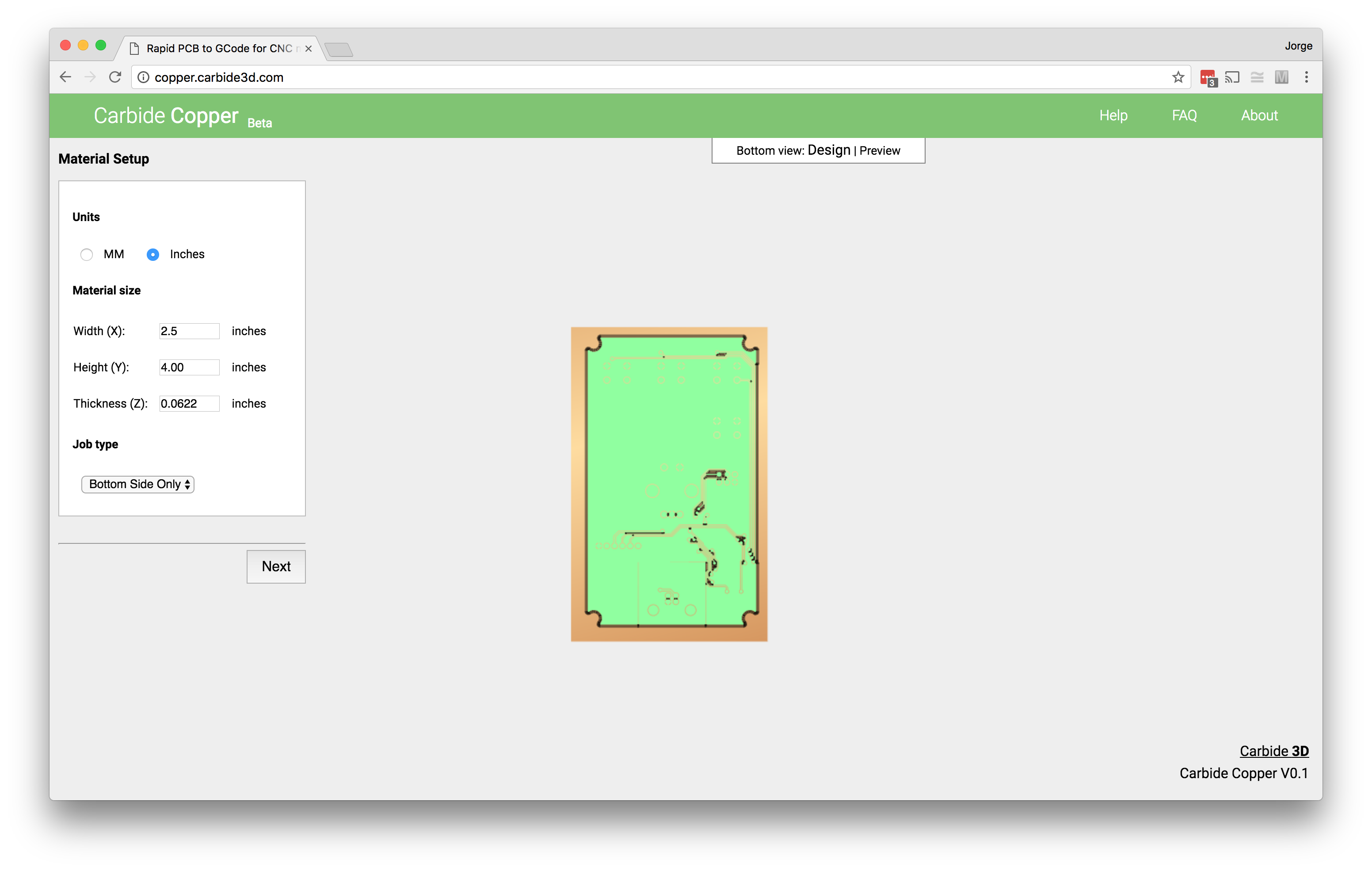
- In the right-hand menu, select inches or millimeters as your preferred units.
- Enter the dimensions under Material Size.
- Under Job Type, select Bottom Side Only
- Click Next.
NOTE: If Bottom Side Only is selected, Carbide Copper will mirror the signal layer
Copper Layer

- Click Choose File
- Navigate to the your gerber file, then click Open. It’ll take a second or two before your file loads in the preview.
NOTE: You can also drag and drop your gerber file into the dotted window.
- Under Tool select the #501 Vee bit.
- Select 3 for the number of Isolation Passes (the number of passes around the edge of the board and between traces).
- Click Next.
Drill Holes

- Click Choose File and navigate to the excellon drill file, then click Open.
- Verify that the drills match the location of pads and vias on the board. If you need to apply an offset you may do so under the Position menu (by default Carbide Copper uses the same offset as the signal layer).
- Select a tool under Drilling, leaving the default Plunge Rate.
- Click Next.
NOTE: You can also drag your drill file and drop it into the dotted window.
Board Routing

- Check the Generate Outline Cut box and enter dimensions for the board cutout.
- Under Tool settings select the #102 endmill to cut the outline.
- Click on Design at the top of the page and verify that the cutout doesn’t interfere with any traces or drills.
- Once satisfied, click Next.
Area Rubout

Area Rubout removes copper from the board that isn’t part of the layout. This is typically required in high frequency or high voltage designs, where the extra copper can alter electrical features. It adds significant machining time and is not necessary for most applications, so we’ll leave Generate Area Rubout unchecked.
- Click Next.
G-code Output

- To save the gcode, Click Generate and save to disk.
- Place the generated nc file in a convenient place on your computer.
Appendix
Built-in Cutters
The following cutters are built into Carbide Cutter:
| Number | Description | Link |
|---|---|---|
| 101 | 1/8" Ball Cutter | Carbide 3D Store |
| 102 | 1/8" Flat Cutter | Carbide 3D Store |
| 111 | 1/16" Ball Cutter | Carbide 3D Store |
| 112 | 1/16" Flat Cutter | Carbide 3D Store |
| 121 | 1/32" Ball Cutter | Carbide 3D Store |
| 122 | 1/32" Flat Cutter | Carbide 3D Store |
| 301 | 90 Degree V Cutter | Carbide 3D Store |
| 302 | 60 Degree V Cutter | Carbide 3D Store |
| 501 | 60 Degree V Cutter, .01" Ball | Carbide 3D Store |
Materials
| Num Sides | Description | Link |
|---|---|---|
| 1 | 2x3" Phenolic PCB | Carbide 3D Store |
| 2 | 2x3" Phenolic PCB | Carbide 3D Store |
| 1 | 4x6" Phenolic PCB | Carbide 3D Store |
| 2 | 4x6" Phenolic PCB | Carbide 3D Store |
Generating Gerber Files from Eagle
To make PCBs with Carbide Copper, we need to export gerber files in 247X format. For this guide we’ll use a single sided board with 10 mil traces and 10 mil isolation. We’ll export gerbers using the Carbide 3D CAM file.
If you do not have the Carbide 3D CAM file for eagle, you can get it here.
Gerber Files
Gerber files are the industry standard format for manufacturing PCBs. They’re a hybrid of machine control language and image that describes each layer of the board. To make things simple, the Carbide 3D CAM file only generates the gerbers we need for milling with the Nomad.
A CAM file tells the CAM processor which layers we want exported as gerbers, and how to create them. The Carbide 3D file creates gerbers for the top and bottom layers, the dimension layer (outline of the board), and a drill file. Note that neither the top or bottom gerbers are mirrored. The files generated by the Carbide 3D CAM file are:
| Extension | Gerber File |
|---|---|
| .TOP | Top Copper |
| .BOT | Bottom Copper |
| .OTL | Outline |
| .TXT | Drill |
| .gpi | Photoplotter Info |
| .dri | Drill Station Info |
NOTE: The .gpi and .dri files are automatically generated by Eagle and can be ignored.
The CAM Processor
Open your board in Eagle, and load the CAM processor by clicking the CAM icon.

The window that pops up should look like this:

Go to the File menu, then go to Open > Job. Select the Carbide3D.cam file and click Process Job.
Once the gerbers are processed you’ll find the files in your project directory.